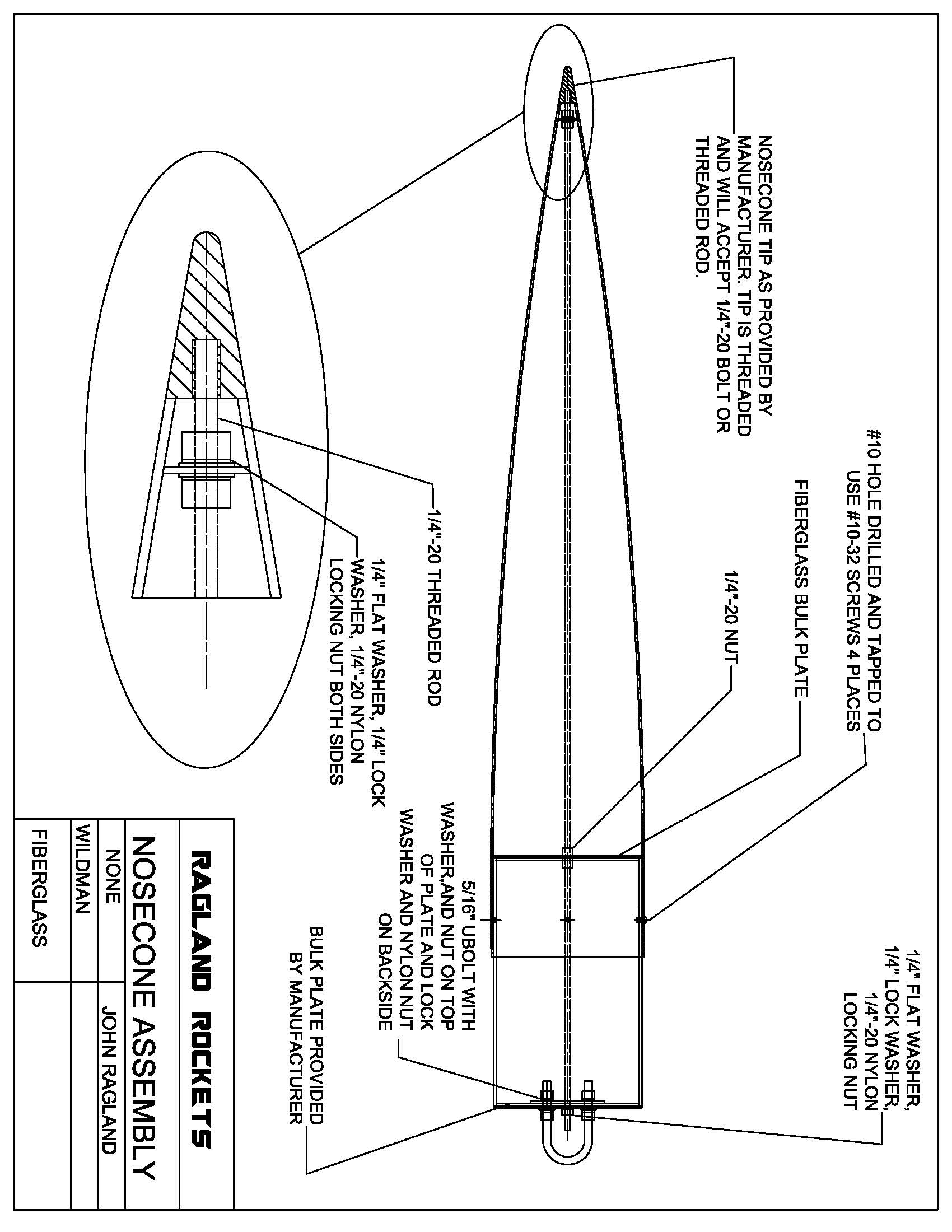
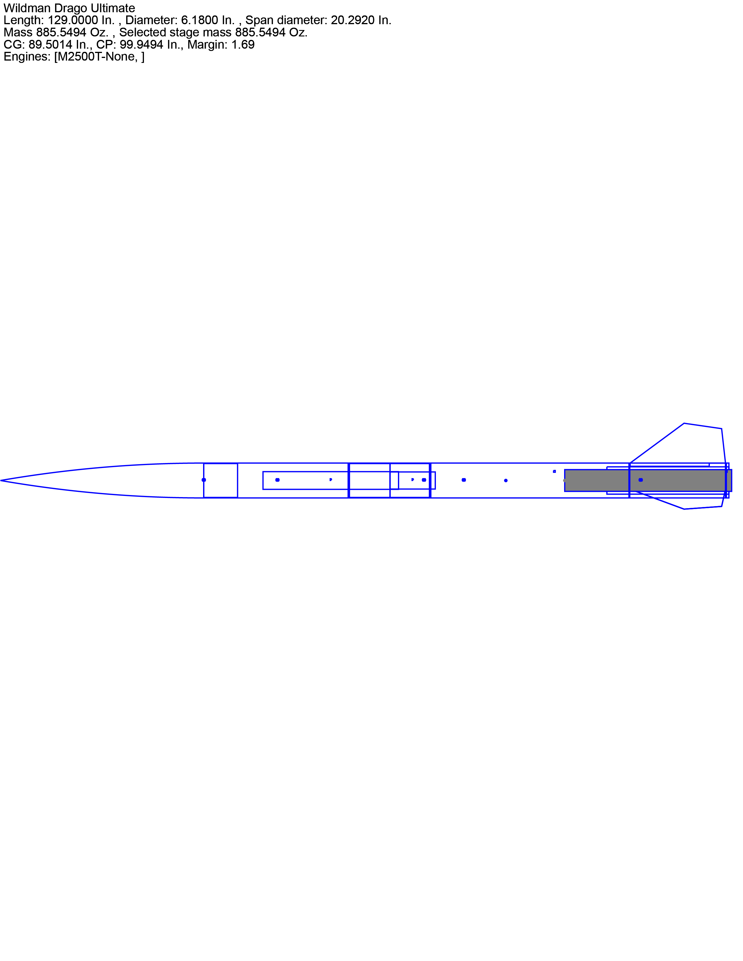
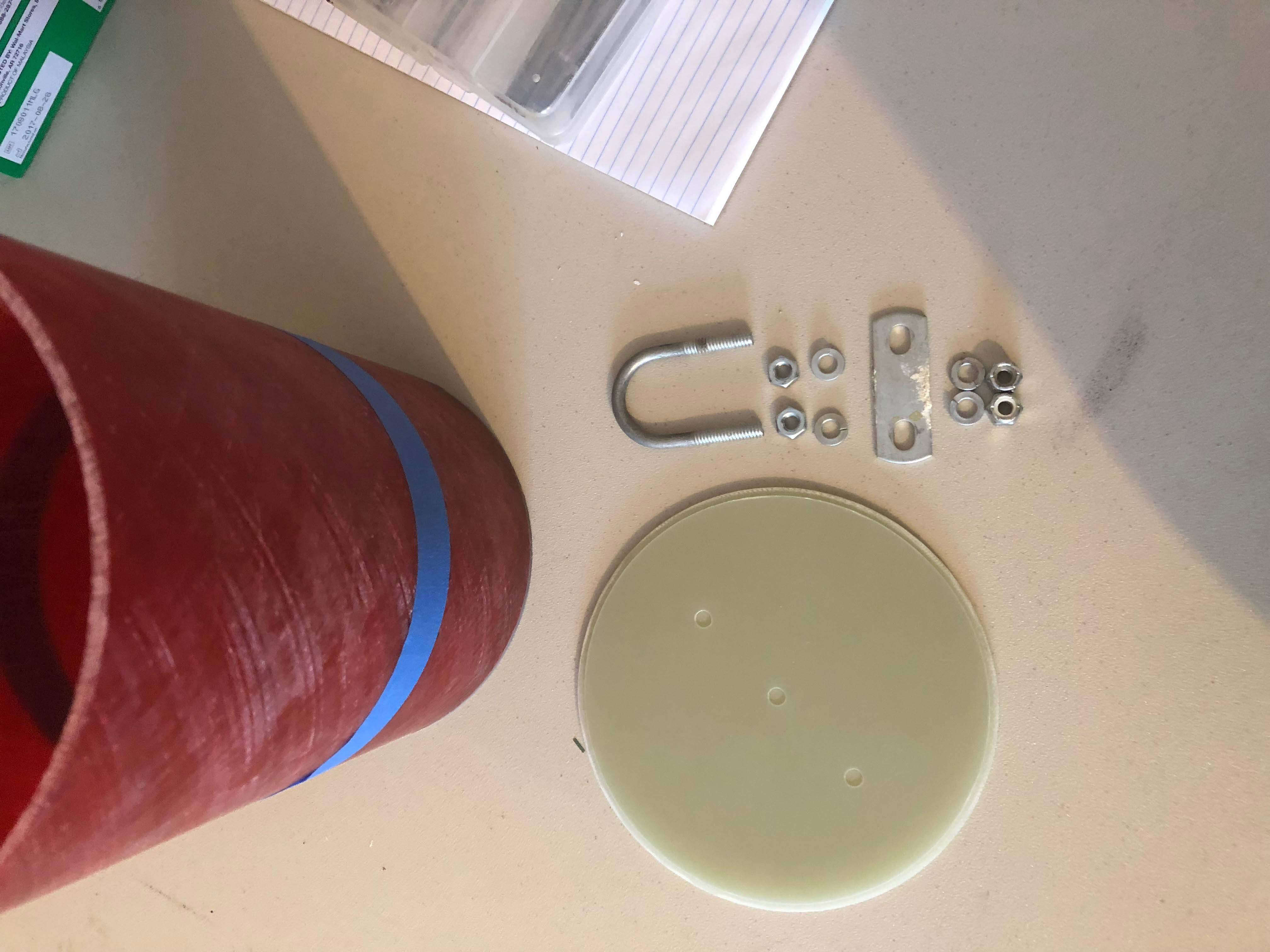
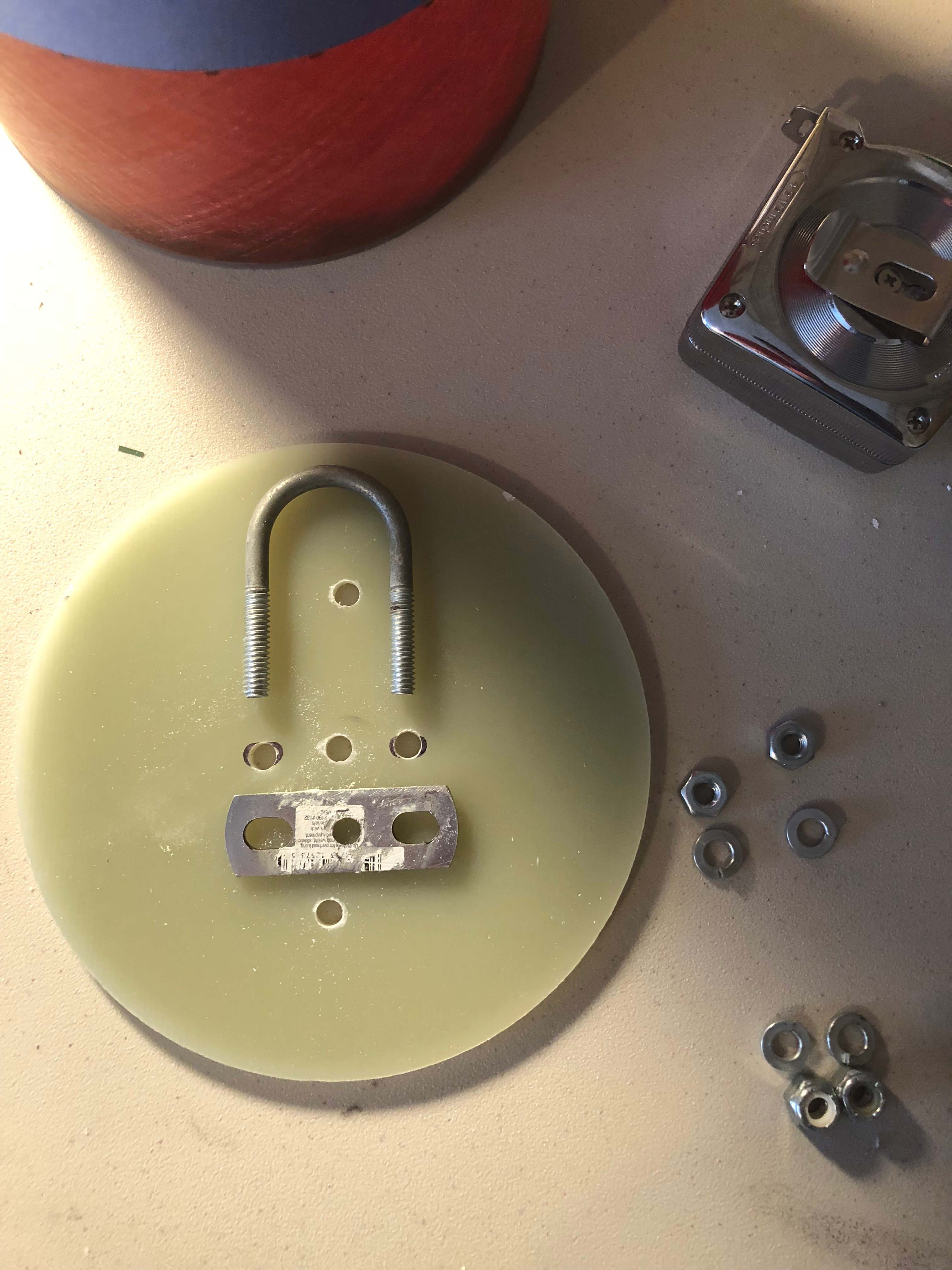
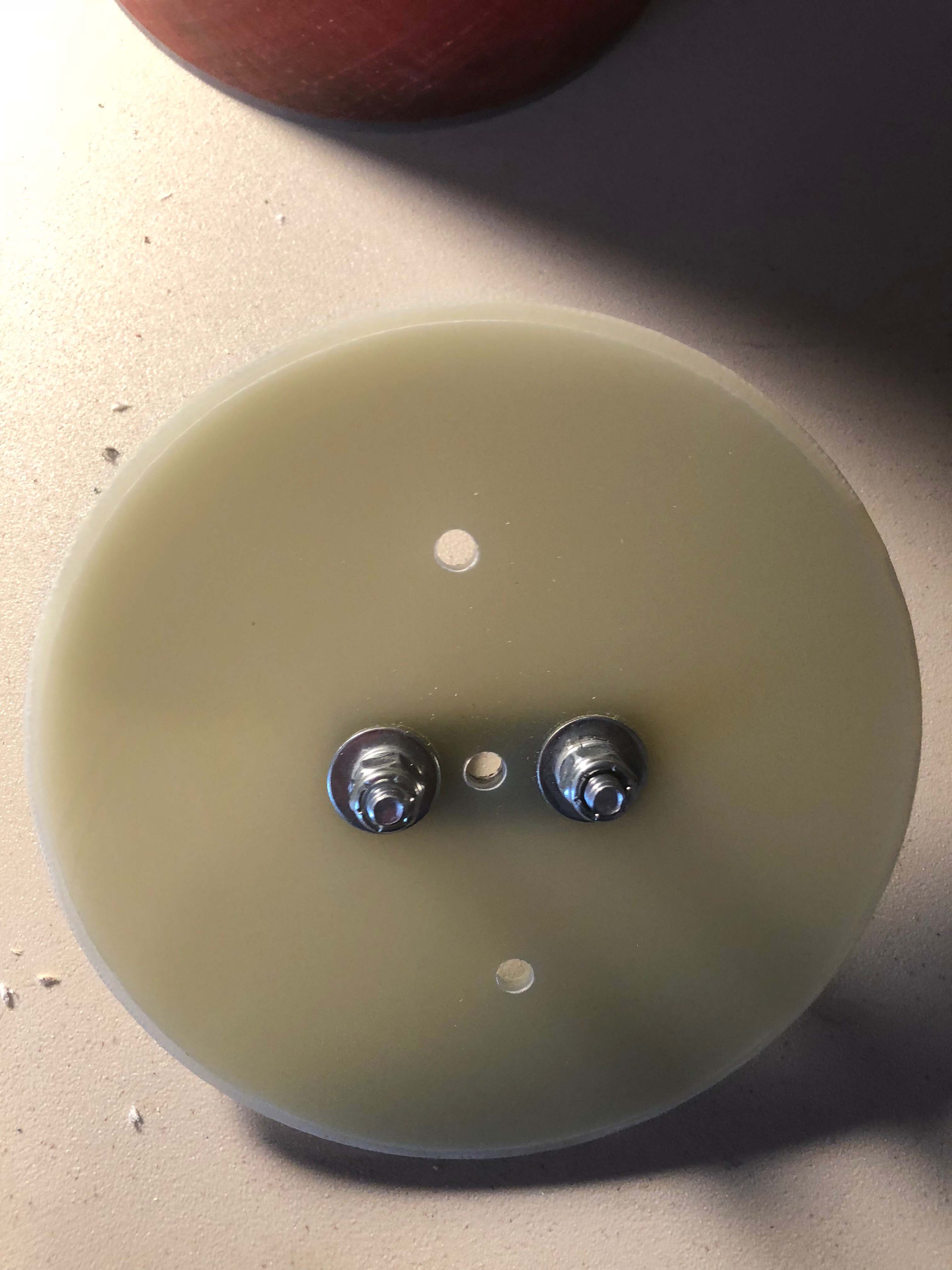
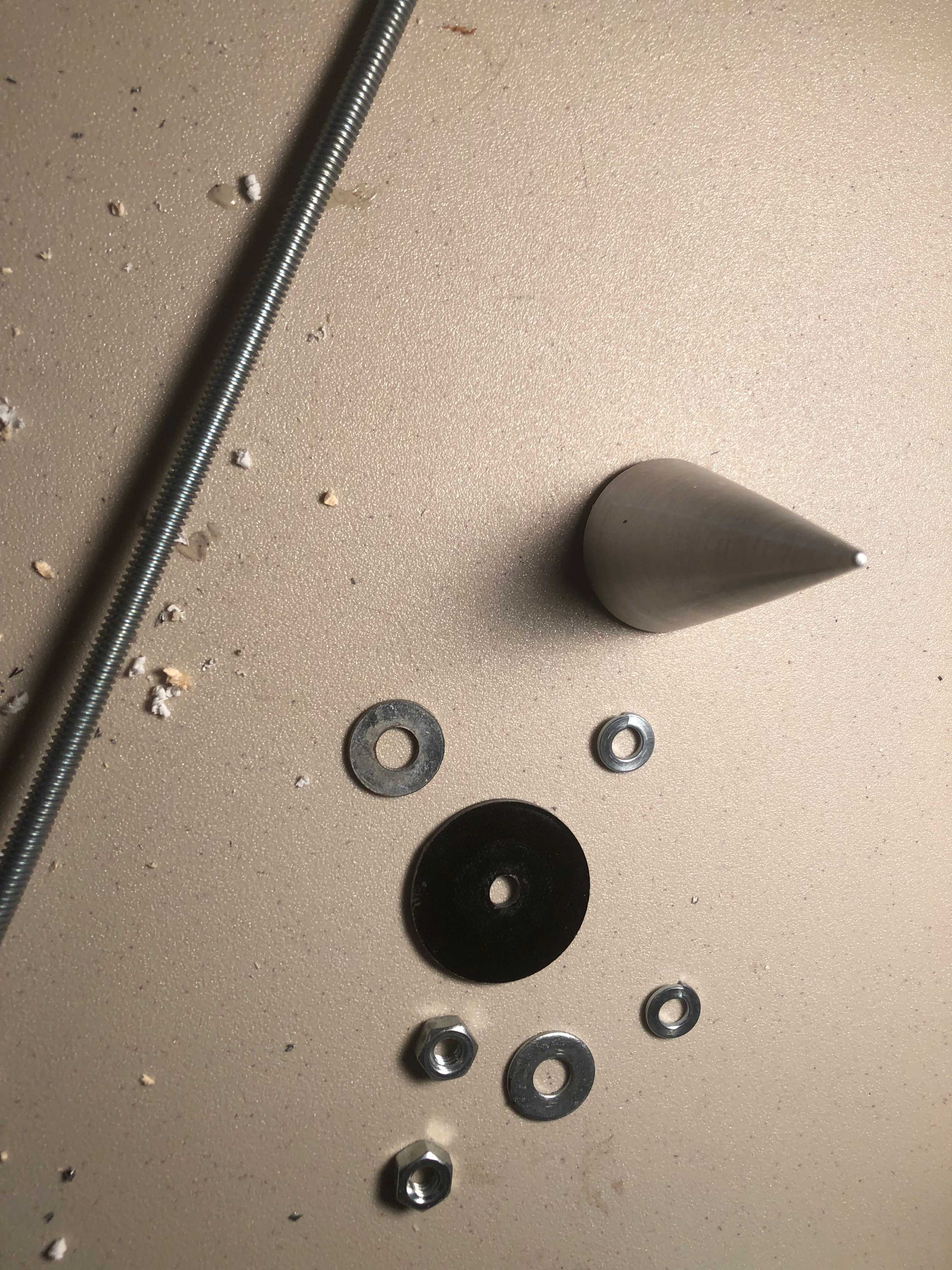
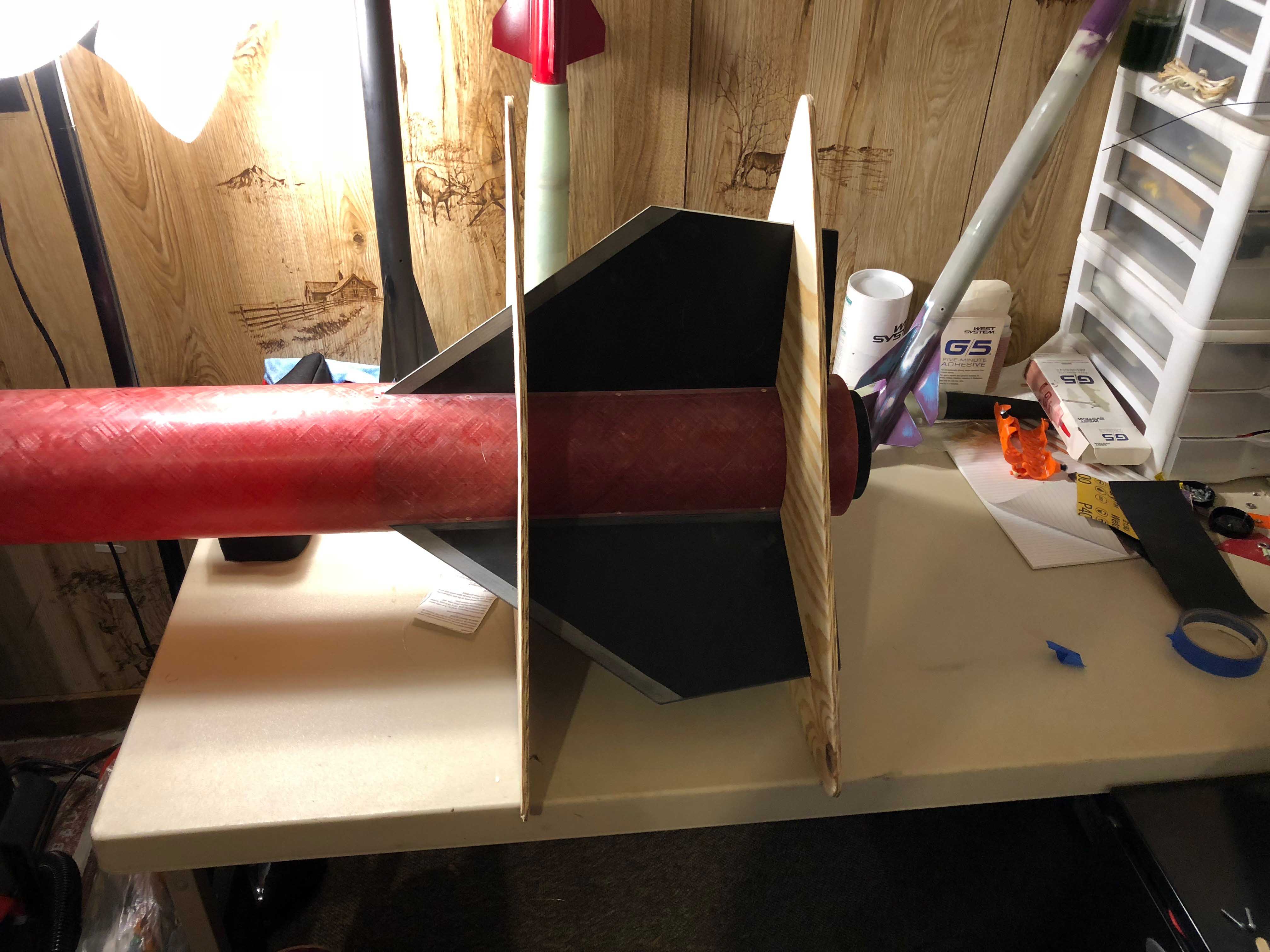
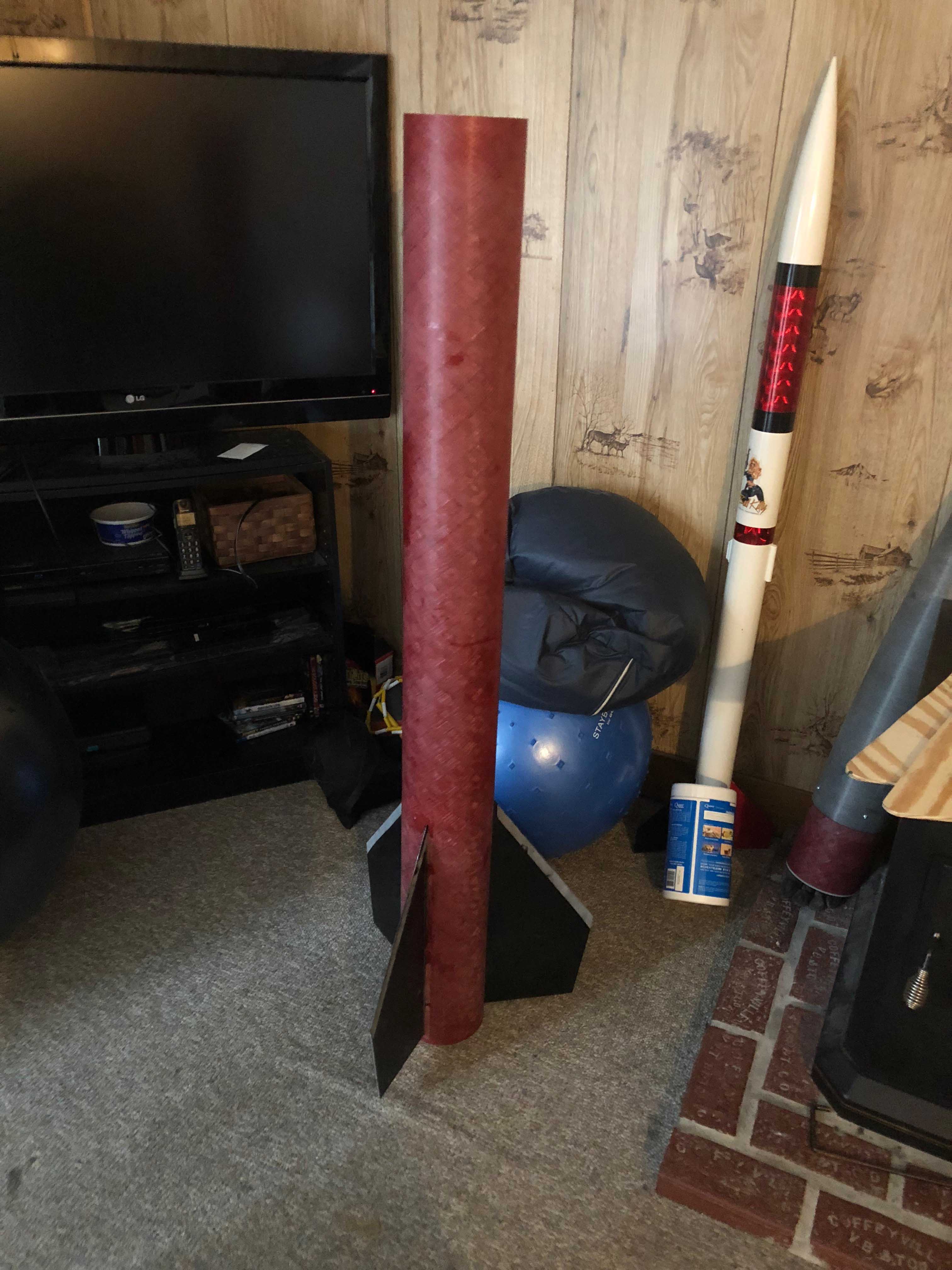
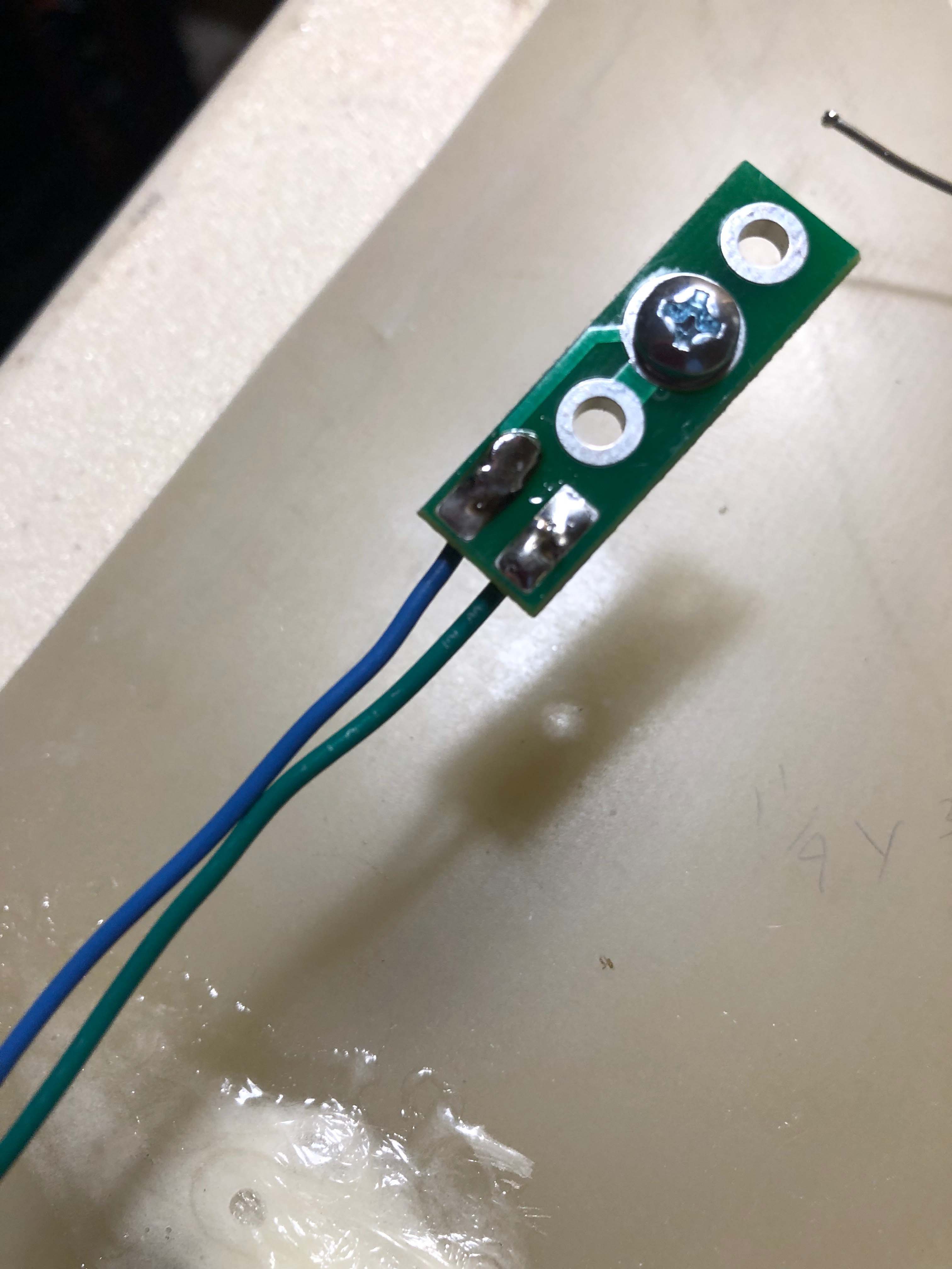
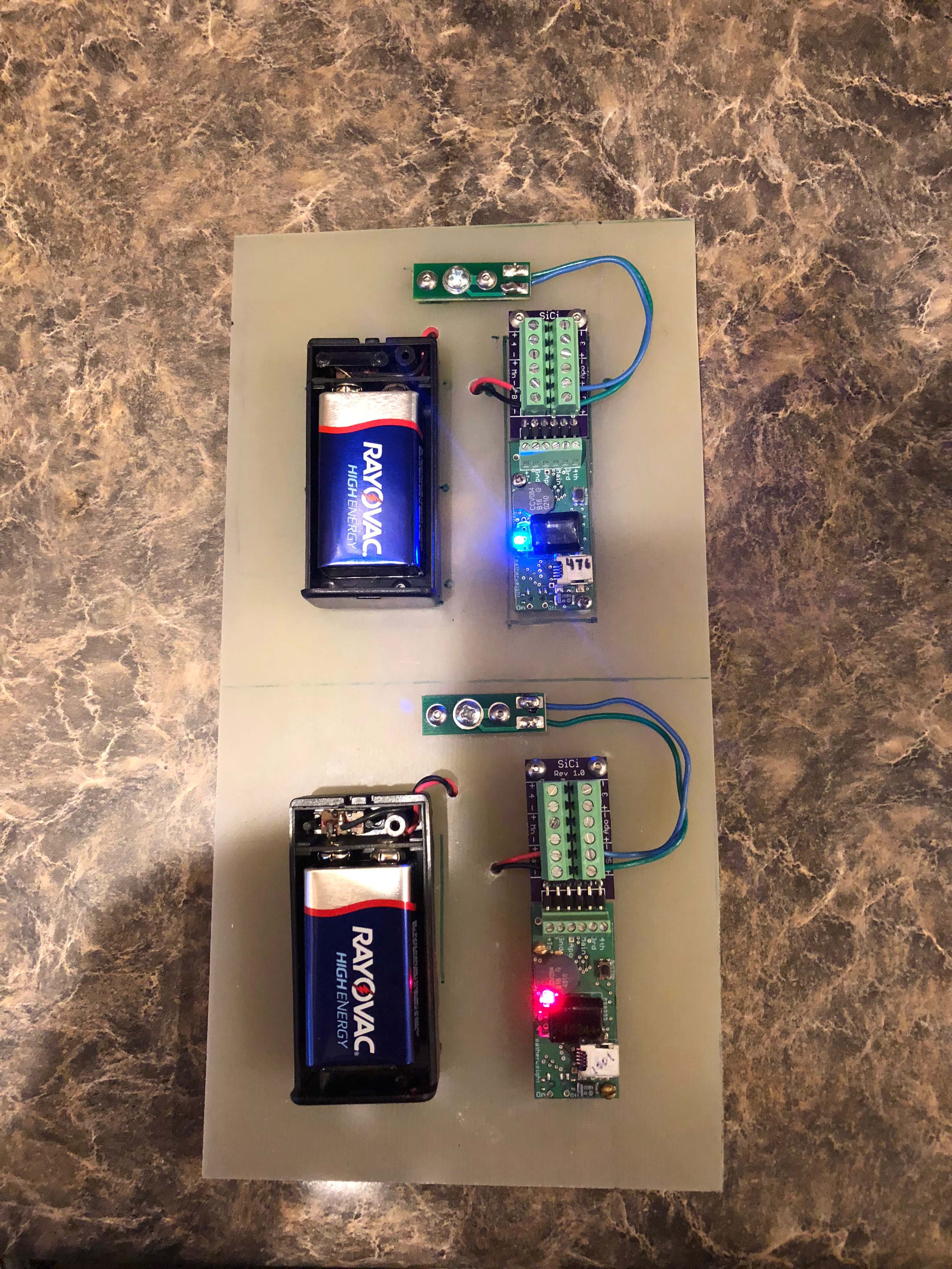
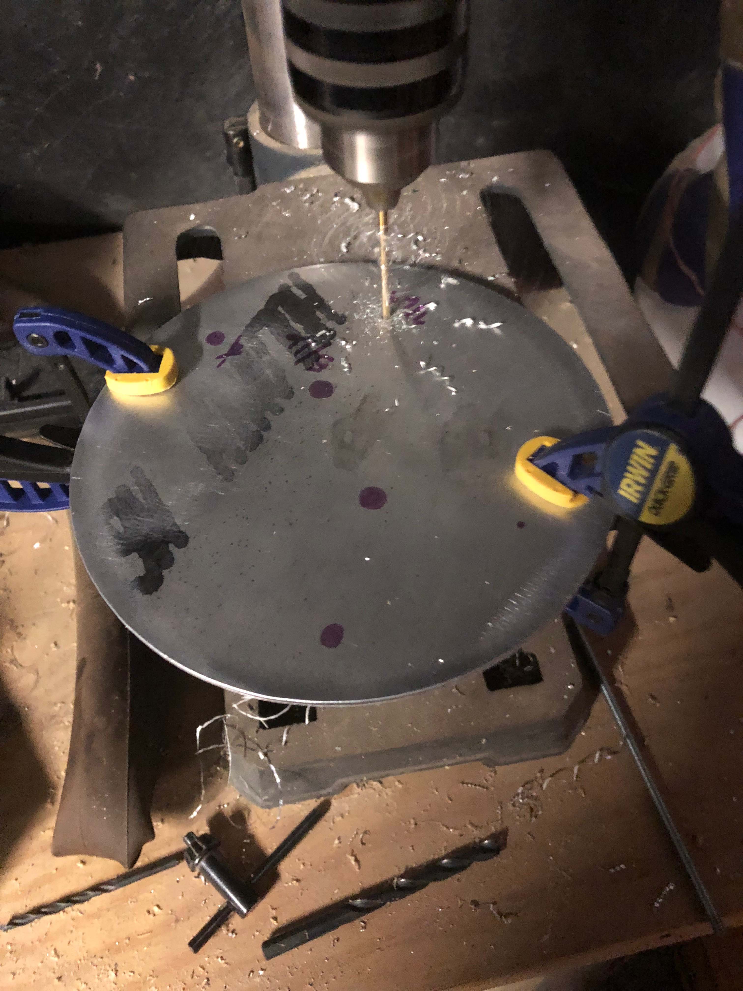
Pre-Build Description of Plans and FlightPre-Build PrintsSimulations for ArgoniaSimulations for PrincetonLaunch Site - Rocket Pasture Argonia Kansas.Launch Site - Quad City - Princeton Illinois.With the sanding done and the centering rings ready to assemble to the motor mount, I use the motor case to make sure the centering ring, motor mount, and retainer are all centered poperly.I mark the holes for the retainer and then remove the centering ring and motor case from the motor mount. With the holes drilled and tapped for the retainer i am now ready to assemble the retain to the rear centering ring. The retainer is assembled to the centering ring using the supplied hardware. With the rear centering ring done I layout my parts and do a dry fit. Things seem to fit. At this point I will start on the nose cone. I will use the bulk plates as part of the design for my nose cone.The bulk plate is epoxied to the forward of the nose cone coupler/shoulder.This is a side view of the nose cone coupler/shoulder.Components for the nose cones rear coupler/shoulder bulk plate.The holes have been drilled in the proper locations for the bulk plate and in the center of the u-bolt flat bar.The U-bolt assembled into the bulk plate.I will utilize this hardware along with the tip of the nose cone as part of the structure for the nose cone bay. The threaded rod will fasten into the tip the same as it came only the threaded rod is longer and will go all the way through the nose cone.The threaded rod assembled and ready to go into the tip of the nose cone as provided.The threaded rod goes all the way from the tip and is used to hold the rear bulk plate in.The nose cone is assembled but not completely finished. I still need to fasten the should to the actual nose coneRather than epoxy the shoulder into the nose cone, i prefer to drill/tap and fasten the shoulder in so that i can work on the nose cone at a later date if needed.4 #10 screws are placed around the nose cone, fastening it to the shoulder. Along with the threaded rod, there isn't much chance of a failure.I used a file and 80 grit sandpaper to scar the motor mount. This will create a better bond between the harness and motor mount.I used a small strip of fiberglass cloth over the harness to add bonding to it and the motor mount.Usage of fiberglass cloth around the centering ring will give the structure more strength. Sure, it looks rough, but no one will see it.I drew a template for my fin guide on Autocad then printed it. I will then cut out 2 fin guides.This is the cut out fin guide. I taped off 3/4" from the fin slot and drilled injection holes and sanded it.With the tape remove I am ready to assemble my fins.The templates work well, but next time I will make a third one that will hold the end of the tube up.Using JB-Weld i secured the root edge to the motor mount. the image looks like there was a gap in places, but there wasn't. I actually got a real good bondInternal fillets are injected. I used chopped fiberglass with the west systems instead of chopped carbon fiber. I did this with the rear centering ring off. This way I could make sure I got a good coverage.Fins are on. I will need to put the rear centering ring on and do extenal fillets on the fins.The fins are taped off and the surfaces are sanded and cleaned. Ready to epoxy.Fillets are struck. I used a mixture of 1/16" milled fiberglass and coloidal silica to thicken the epoxy and give it strength. It is a bit rough, So later I will come back with a thin coat of West Systems G5 to give the fillets a smooth look.Tape removedTape removedEjection charges will be held inside blast containers made of PVC caps.It's time for a break. The wife and I took some time to enjoy a rootbeer float.Soldered the switch. I still am not the worlds best at soldering but I am much better at it due to tips I got years back from Greg Rothman.The sled all set up and being tested.Drilling the avbay lids.The avbay all set up and ready to go into the airframe.Marking lines for sampling holes and screws to hold the avbay into its location. The top hole will be covered since it isn't needed. I drilled 4 1/4" sampling holes.MarkedDrilled and TappingDrilled, Tapped, AssembledOnly a few things left and I can fly it.